Product Series
![]()
-
Coupling diaphragm
-
Diaphragm coupling
-
Drum gear coupling
-
Tyre coupling
-
Plum elastic coupling
-
Star flexible coupling
-
Elastic pin coupling
-
Elastic sleeve pin coupling
-
Elastic pin gear coupling
-
Serpentine spring coupling
-
Roller chain coupling
-
Clamping coupling
-
Flange coupling
-
Slider coupling
-
H-type flexible coupling
-
Coupling accessories
Company News
MORE
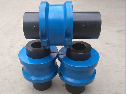
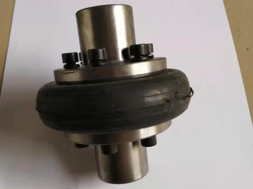
UL tire coupling


UL tire coupling product description or use:
ULTyre couplingIt is composed of half coupling, bolts, tire ring, backstop plate, etc. The tire ring is a combination of rubber, cord rubber composite material, hoops and frame, which is made by vulcanization and bonding.This kind of coupling has the performance of compensating the relative displacement of the two shafts and buffering and damping vibration. At the same time, the installation is also relatively convenient. There is no need to move the coupling axially when changing the tire ring.
UL tire coupling is a highly elastic coupling with good shock absorption and good performance of offset compensation between shafts. The working temperature is -20~80 degrees Celsius, and the transmission torque is 10~25000N.m. It is suitable for The working conditions are humid, dusty, shock, vibration, forward and reverse, and frequent starting. It is easy to disassemble and assemble. Because the elastic element is an integral tire body, it is convenient to disassemble and maintain without lubrication and is reliable.
main feature:
1. The standard half-coupling structure is type K, which can no longer be marked in the display.
2. The rubber element (tyre body) is vulcanized and bonded to the metal pressure plate, and the two halves of the coupling are directly connected with bolts during assembly.
3. Flexible, large damping, and large compensation.
4. The structure is simple and easy to assemble. There is no need to move the coupling axially when changing the tire body.
5. Disadvantages: With the increase of the torsion angle, considerable axial force will be generated on the driving and driven shafts.

| model | Allowable torque Tn Nm | Instantaneous high torque | Allowable speed [n]r/min | Diameter of shaft hole | Length of shaft hole | D | B | Mass Kg | Moment of inertia kg.m2 | |
| J J1 | Y | |||||||||
| d | L | |||||||||
| UL1 | 10 | 31.5 | 5000 | 11-18 | 22-30 | 25-42 | 80 | 20 | 0.7 | 0.0003 |
| UL2 | 25 | 80 | 5000 | 14-22 | 27-38 | 32-52 | 100 | 26 | 1.2 | 0.0008 |
| UL3 | 63 | 180 | 4500 | 18-25 | 30-44 | 42-62 | 120 | 32 | 1.8 | 0.0022 |
| UL4 | 100 | 315 | 4300 | 20-30 | 38-60 | 52-82 | 140 | 38 | 3.0 | 0.0044 |
| UL5 | 160 | 500 | 4000 | 24-35 | 38-60 | 52-82 | 160 | 45 | 4.6 | 0.0084 |
| UL6 | 250 | 710 | 3600 | 28-40 | 44-84 | 62-112 | 180 | 50 | 7.1 | 0.0164 |
| UL7 | 315 | 900 | 3200 | 32-48 | 60-84 | 82-112 | 200 | 56 | 10.9 | 0.0290 |
| UL8 | 400 | 1250 | 3000 | 38-50 | 60-84 | 82-112 | 220 | 63 | 13.0 | 0.0448 |
| UL9 | 630 | 1800 | 2800 | 42-60 | 84-107 | 112-142 | 250 | 71 | 20.0 | 0.0898 |
| UL10 | 800 | 2240 | 2400 | 45-70 | 84-107 | 112-142 | 280 | 80 | 30.6 | 0.1596 |
| UL11 | 1000 | 2500 | 2100 | 50-75 | 84-107 | 112-142 | 320 | 90 | 39 | 0.2792 |
| UL12 | 1600 | 4000 | 2000 | 55-85 | 84-132 | 112-172 | 360 | 100 | 59 | 0.5356 |
| UL13 | 2500 | 6300 | 1800 | 63-95 | 107-132 | 142-172 | 400 | 110 | 81 | 0.8960 |
| UL14 | 4000 | 10000 | 1600 | 75-110 | 107-167 | 142-212 | 480 | 130 | 145 | 2.2616 |
| UL15 | 6300 | 14000 | 1200 | 85-125 | 132-167 | 172-212 | 560 | 150 | 222 | 4.6456 |
| UL16 | 10000 | 20000 | 1000 | 100-140 | 167-202 | 212-252 | 630 | 180 | 302 | 8.0924 |
| UL17 | 16000 | 31500 | 900 | 120-160 | 167-242 | 212-302 | 750 | 210 | 561 | 20.0176 |
| UL18 | 25000 | 59000 | 800 | 140-180 | 202-242 | 252-302 | 900 | 250 | 818 | 43.0530 |