categories of news
![]()
Popular products
MORE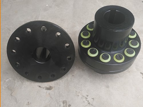
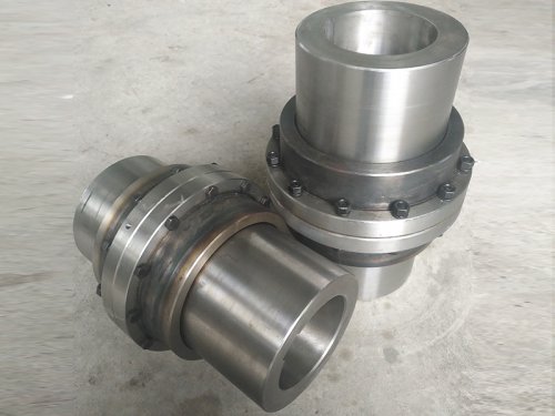
Main problems to be solved in the diaphragm coupling of the main oil pump of the steam turbine
At present, there is still a very limited number of diaphragm couplings in China. The stress distribution on the diaphragm of the diaphragm coupling under the separate action of torque and centrifugal force load respectively, and the influence of their changes on the stress on the diaphragm is analyzed and compared. And its degree of influence.The calculation results show that the stress value at each point increases when the torque increases, but its value does not change much, that is, the torque change has little effect on the stress on the diaphragm, and the stress value generated by the torque load in the diaphragm is equal to The number of diaphragm layers is inversely proportional, so the number of diaphragm layers can be estimated based on the small torque.The speed change is the main factor that affects the stress on the diaphragm.For centrifugal load, the key is to handle the restraint conditions, which mainly depends on the position of the center of mass, the mass and the stiffness of the bolt and its connecting parts.The greater the rigidity, the smaller the deformation of the bolt.When the restriction on the inner half circumference of the diaphragm screw hole increases, the stress decreases; conversely, when the restriction on the outer half circumference of the diaphragm screw hole increases, the stress value increases.Therefore, the higher the operating speed, the greater the rigidity of the bolt and its connecting parts should be designed.
In addition, try to place the total center of mass of the bolt connection near the intersection of the middle diaphragm and the bolt axis of the diaphragm assembly, and analyze and calculate the stress of the diaphragm during the design to ensure the use.The calculated results have a reference for the design of the diaphragm assembly of the diaphragm coupling.At the same time, the vibration characteristics of the diaphragm coupling have been done. The results show that the axial natural frequency of the diaphragm coupling is low, so the possibility of axial resonance during operation is less.When the coupling is unbalanced, the natural frequency of the system will decrease, and the greater the unbalance, the lower the natural frequency.Therefore, it is necessary to increase the speed of the coupling and improve the accuracy of the dynamic unbalance of the coupling.In order to improve the balance accuracy of the coupling, the mass eccentricity of the coupling is usually corrected by a dynamic balancing machine to reduce its eccentric quality and improve the balance accuracy of the coupling.
Diaphragm coupling damage is one of the more common failures of the main oil pump of a steam turbine. 60% of the diaphragm coupling failures are related to shaft misalignment.Causes equipment vibration, bearing wear, coupling deflection, steam turbine start-up expansion and deformation, etc.
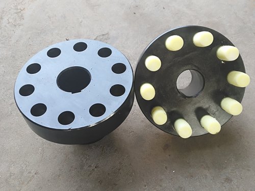
There are two main reasons for coupling damage, dynamic imbalance and misalignment of assembly.These two factors usually exist at the same time and work together. In order to reduce the vibration and fatigue damage of the diaphragm coupling, this paper makes a theoretical analysis of the alternating stress of the diaphragm and the vibration mechanism of the coupling, and proposes to use 6 holes The scheme of replacing the 4-hole diaphragm with a diaphragm has also increased the number of layers of the diaphragm, and verified the feasibility and rationality of the structure with actual operating results, and proposed guiding measures to reduce vibration and increase the life of the diaphragm.
The work of this paper mainly consists of the following parts:
(1) The axial and angular deviations caused by assembly misalignment and vibration during operation have a great influence on the life of the coupling. The stress of the diaphragm and accessories under various loads will be analyzed in detail. The structure of the diaphragm and accessories is optimized, which reduces the working stress of the diaphragm.
(2) When rotating at high speed, the coupling unit will produce a lot of vibration, which is a great threat to the stable operation of the coupling. This paper has specially designed the structure of the coupling, which greatly reduces the operation of the coupling. Time of vibration.
(3) The bolt of the coupling is the key component of the coupling that connects the diaphragm and the flange. It is the vulnerable part of the coupling. Its correct installation is the key to ensuring the performance of the coupling. This paper passed The correct installation method of bolts is analyzed, and the correct guidance is provided for the maintenance of the front line.
(4) In order to ensure the installation and use of the diaphragm coupling, the sliding pin of the steam turbine is also optimized to provide a guarantee for the stable operation of the coupling.
With the development of steam turbine equipment, the power connection of various parts of the steam turbine has attracted more and more attention in the industry.The coupling between the drive shaft and the driven shaft is usually realized through a coupling. In actual use, there must be various misalignments between the drive shaft and the driven shaft. After the machine is running, these misalignments will affect the power transmission and The connection has a negative impact, so the analysis of the strength characteristics and dynamic characteristics of the coupling is particularly important.
If there is a significant dynamic imbalance or assembly misalignment, the vibration caused will be very large, so that the vibration of the coupling becomes the main vibration source of the system.
The relative displacement between the drive shaft and the passive shaft is absorbed by the flexibility of the diaphragm material. The reason why the diaphragm coupling is widely used is that it has the advantages of no lubrication, no maintenance, no noise, and failure protection. Constantly low unbalance, can operate in a harsh environment, and can be disassembled and assembled without disturbing the master and slave machinery, and a series of advantages.
Because the diaphragm of the diaphragm coupling has good flexibility, it can adapt to the misalignment condition of the axis between the main and the slave parts of the connected parts.This adaptability can be achieved by adjusting the number of diaphragm sets of the diaphragm coupling, the structure of the diaphragm and the intermediate shaft, because the elastic diaphragm has good flexibility and only consumes when compensating for the misalignment between the master and the slave. With little deformation energy, it will not cause excessive load on the crankshaft.
The diaphragm coupling is designed with a protective ring or shaft head gasket structure. Even when the entire set of diaphragms fails completely, the protective ring can prevent a large radial displacement of the intermediate shaft.
Because there is no circumferential and radial clearance, severe friction and wear will not occur, and the original dynamic balance can be maintained for a long time.Through reasonable design and use conditions, the symmetry of the structure can balance the coupling itself without the need to lubricate the rotating parts of the shaft.Therefore, a diaphragm coupling that is generally dynamically balanced can maintain a dynamic balance during the entire operating cycle.
Due to the structural characteristics, the diaphragm coupling can adapt to most working environments. It can operate at low temperatures below 0°C and also at temperatures above 300°C: when the parts are made of corrosive materials, they can be used It operates in corrosive atmosphere; its structure is basically not affected by the atmospheric pressure of the environment, so it can operate in plateau or vacuum conditions, or in a high-pressure closed container; the diaphragm has good elasticity and its own vibration absorption and vibration isolation effect, which can withstand Various vibrations and shocks.The coupling in this article works under an oil temperature environment of 40~45℃.
The diaphragm main oil pump coupling without an intermediate shaft is an intelligent flexible shaft. For a rotating shaft with a relatively high rigidity supported by multiple fulcrums, the coupling without intermediate shaft can be used to decompose it into several double-support series systems, thereby reducing Its overall rigidity can not only reduce the coaxiality requirements of the supporting points, so as to reduce the occurrence of positioning constraint conditions, and at the same time, the reduction of the rotor rigidity can also change the natural frequency.
The typical axial stiffness curve of diaphragm coupling, the axial stiffness is zero when the initial position is zero deflection, and it increases non-linearly with the increase of the deflection.This kind of non-linear elastic characteristic has obvious detuning and vibration reduction damping effect, and it is not easy to cause gradually increased resonance, so the possibility of large-scale axial vibration of the diaphragm coupling is very small, which makes this type of coupling It can be adapted to the environment where the main oil pump part of the steam turbine moves in a large axial direction.
Due to the low quality of the diaphragm coupling and the good flexibility of the metal diaphragm, the additional load of the coupling to the connected unit is small during operation, so the diaphragm coupling can support the entire main oil pump system after the diaphragm coupling. load.Because the steam turbine unit is dynamic during operation, the displacement occurs continuously and has time domain characteristics.
There is no gap between the parts of the diaphragm coupling, there is almost no friction and sliding loss during work, and the structure has a relatively large circumferential rigidity.