Product Description
Product Description
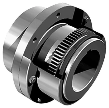
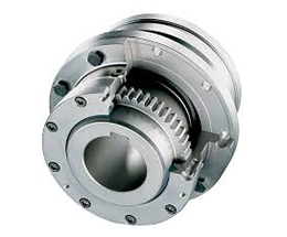
Hot Selling GL Type Spline Rigid Shaft Couplings Roller Chain Coupling For Industry Machine
FEATURES
Manufactured according to relevant industrial standards
Available in many sizes, ratings, and product types, including flexible shaft couplings and OK couplings
Fabricated from a variety of high-grade steel
BENEFITS
Several surface treatment processes protect against corrosion
Customized products are available
Large couplings withstand very high torque
Flexible shaft couplings compensate for shaft misalignment
The chain coupling consists of two-strand roller chains, 2 sprockets and AL-Alloy cover, features simple and compact structure, and high flexibility, power transmission capability and durability.
What’s more ,the chain coupling allows simple connection/disconnection, and the use of the housing enhances safety and durability.
The number of roller depends CHINAMFG the specific application
| Chain No. | Pitch
P mm |
Roller diameter d1max mm |
Width between inner plates b1min mm |
Pin diameter d2max mm |
Pin length | Inner plate depth h2max mm |
Plate thickness
Tmax mm |
Tensile strength
Qmin kN/lbf |
Average tensile strength
Q0 |
Weight per meter q kg/m |
|
| Lmax
mm |
Lcmax
mm |
||||||||||
| 08AF36 | 12.700 | 7.95 | 21.70 | 3.96 | 30.8 | 32.1 | 12.00 | 1.50 | 13.8/3135.36 | 16.20 | 1.070 |
| 10AF13 | 15.875 | 10.16 | 16.31 | 5.08 | 27.6 | 29.1 | 15.09 | 2.03 | 22.2/5045 | 27.50 | 1.350 |
| 10AF71 | 15.875 | 10.16 | 19.00 | 5.08 | 30.5 | 32.2 | 15.09 | 2.03 | 21.8/4901 | 24.40 | 1.480 |
| *10AF75 | 15.875 | 10.16 | 45.60 | 5.08 | 57.0 | 58.5 | 15.09 | 2.03 | 21.8/4901 | 24.40 | 2.540 |
| 12AF2 | 19.050 | 11.91 | 19.10 | 5.94 | 32.6 | 34.4 | 18.00 | 2.42 | 31.8/7227 | 38.20 | 1.900 |
| 12AF6 | 19.050 | 11.91 | 18.80 | 5.94 | 31.9 | 33.5 | 18.00 | 2.42 | 31.8/7227 | 38.20 | 1.870 |
| 12AF26 | 19.050 | 11.91 | 19.36 | 5.94 | 31.9 | 33.5 | 18.00 | 2.42 | 31.8/7227 | 38.20 | 1.940 |
| 12AF34 | 19.050 | 11.91 | 19.00 | 5.94 | 31.9 | 31.9 | 18.00 | 2.42 | 31.1/7066 | 38.20 | 1.860 |
| 12AF54 | 19.050 | 11.91 | 19.50 | 5.84 | 31.9 | 31.9 | 18.00 | 2.29 | 31.1/7066 | 38.20 | 1.607 |
| *12AF97 | 19.050 | 11.91 | 35.35 | 5.94 | 48.8 | 50.5 | 18.00 | 2.42 | 31.8/7149 | 38.20 | 2.630 |
| *12AF101 | 19.050 | 11.91 | 37.64 | 5.94 | 51.2 | 52.9 | 18.00 | 2.42 | 31.8/7149 | 38.20 | 1.990 |
| *12AF124 | 19.050 | 11.91 | 20.57 | 5.94 | 33.9 | 35.7 | 18.00 | 2.42 | 31.8/7149 | 38.20 | 1.910 |
| 16AF25 | 25.400 | 15.88 | 25.58 | 7.92 | 42.4 | 43.9 | 24.00 | 3.25 | 56.7/12886 | 63.50 | 3.260 |
| *16AF40 | 25.400 | 15.88 | 70.00 | 7.92 | 87.6 | 91.1 | 24.00 | 3.25 | 56.7/12886 | 63.50 | 5.780 |
| *16AF46 | 25.400 | 15.88 | 36.00 | 7.92 | 53.3 | 56.8 | 24.00 | 3.25 | 56.7/12886 | 63.50 | 3.880 |
| *16AF75 | 25.400 | 15.88 | 56.00 | 7.92 | 73.5 | 76.9 | 24.00 | 3.25 | 56.7/12746 | 63.50 | 5.110 |
| *16AF111 | 25.400 | 15.88 | 45.00 | 7.92 | 62.7 | 65.8 | 24.00 | 3.25 | 56.7/12746 | 63.50 | 4.480 |
| *16AF121 | 25.400 | 15.88 | 73.50 | 7.92 | 91.3 | 94.7 | 24.00 | 3.25 | 56.7/12746 | 63.50 | 6.000 |
*The number of roller depends CHINAMFG the specific application
| Chain No. | Pitch P mm |
Roller diameter d1max mm |
Width between inner plates b1min mm |
Pin diameter d2max mm |
Pin length | Inner plate depth h2max mm |
Plate thickness
Tmax mm |
Tensile strength
Qmin kN/lbf |
Average tensile strength
Q0 kN |
Weight per meter q kg/m |
|
| Lmax
mm |
Lcmax
mm |
||||||||||
| *20AF44 | 31.750 | 19.05 | 32.00 | 9.53 | 53.5 | 57.8 | 30.00 | 4.00 | 86.7/19490 | 99.70 | 4.820 |
| *24AF27 | 38.100 | 22.23 | 75.92 | 11.10 | 101.0 | 105.0 | 35.70 | 4.80 | 124.6/28571 | 143.20 | 9.810 |
| *06BF27 | 9.525 | 6.35 | 18.80 | 3.28 | 26.5 | 28.2 | 8.20 | 1.30 | 9.0/2045 | 9.63 | 0.770 |
| *06BF31 | 9.525 | 6.35 | 16.40 | 3.28 | 23.4 | 24.4 | 8.20 | 1.30 | 9.0/2045 | 9.63 | 0.660 |
| *06BF71 | 9.525 | 6.35 | 16.50 | 3.28 | 24.5 | 25.6 | 8.20 | 1.30 | 9.0/2571 | 9.63 | 0.830 |
| 08BF97 | 12.700 | 8.51 | 15.50 | 4.45 | 24.8 | 26.2 | 11.80 | 1.60 | 18.0/4989.6 | 19.20 | 0.980 |
| *08BF129 | 12.700 | 8.51 | 35.80 | 4.45 | 45.1 | 46.1 | 11.80 | 1.60 | 18.0/4989.6 | 19.02 | 1.500 |
| 10BF21 | 15.875 | 10.16 | 42.83 | 5.08 | 52.7 | 54.1 | 14.70 | 1.70 | 22.0/5000 | 25.30 | 2.260 |
| 10BF43 | 15.875 | 7.03 | 27.80 | 5.08 | 39.0 | 40.6 | 14.70 | 2.03 | 22.4/5090 | 25.76 | 1.140 |
| *10BF43-S | 15.875 | 10.00 | 27.80 | 5.08 | 39.0 | 40.6 | 14.70 | 2.03 | 22.4/5090 | 25.76 | 1.800 |
| *16BF75 | 25.400 | 15.88 | 27.50 | 8.28 | 47.4 | 50.5 | 21.00 | 4.15/3.1 | 60.0/13488 | 66.00 | 3.420 |
| *16BF87 | 25.400 | 15.88 | 35.00 | 8.28 | 54.1 | 55.6 | 21.00 | 4.15/3.1 | 60.0/13488 | 66.00 | 3.840 |
| *16BF114 | 25.400 | 15.88 | 49.90 | 8.28 | 69.0 | 72.0 | 21.00 | 4.15/3.1 | 60.0/13488 | 66.00 | 4.740 |
| *20BF45 | 31.750 | 19.05 | 55.01 | 10.19 | 76.8 | 80.5 | 26.40 | 4.5/3.5 | 95.0/21356 | 104.50 | 6.350 |
| *24BF33 | 38.100 | 25.40 | 73.16 | 14.63 | 101.7 | 106.2 | 33.20 | 6.0/4.8 | 160.0/35968 | 176.00 | 11.840 |
Advantages:
1. Material: C45 steel, Aluminum, Rubber and plastic etc.
2. High efficiency in transmission
3. Finishing: blacken, phosphate-coat, and oxidation.
4. Different models suitable for your different demands
5. Application in wide range of environment.
6. Quick and easy mounting and disassembly.
7. Resistant to oil and electrical insulation.
8. Identical clockwise and anticlockwise rotational characteristics.
9. Small dimension, low weight, high transmitted torque.
10. It has good performance.
| Partnerships Reliable Supply-Chain: |
Based on our experienced team and strict, effective supply chain management, Granville products deliver premium quality, and performance our customers have relied on for years. From a full range of bearings, mounted bearing units, power transmission products, and related markets around the world, we provide the industry’s most comprehensive range of qualified products available today.
Advantage Manufacturing Processesand Quality Control:
01 Heat Treatment
02 Centerless Grinding Machine 11200 (most advanced)
03 Automatic Production Lines for Raceway
04 Automatic Production Lines for Raceway
05 Ultrasonic Cleaning of Rings
06 Automatic Assembly
07 Ultrasonic Cleaning of Bearings
08 Automatic Greasing, Seals Pressing
09 Measurement of Bearing Vibration (Acceleration)
10 Measurement of Bearing Vibration (Speed)
11 Laser Marking
12 Automatic Packing
1 Prevent from damage.
2. As customers’ requirements, in perfect condition.
3. Delivery : As per contract delivery on time
4. Shipping : As per client request. We can accept CIF, Door to Door etc. or client authorized agent we supply all the necessary assistant.
FAQ
Q 1: Are you a trading company or a manufacturer?
A: We are a professional manufacturer specializing in manufacturing various series of couplings.
Q 2:Can you do OEM?
Yes, we can. We can do OEM & ODM for all the customers with customized artworks in PDF or AI format.
Q 3:How long is your delivery time?
Generally, it is 20-30 days if the goods are not in stock. It is according to quantity.
Q 4: How long is your warranty?
A: Our Warranty is 12 months under normal circumstances.
Q 5: Do you have inspection procedures for coupling?
A:100% self-inspection before packing.
Q 6: Can I have a visit to your factory before the order?
A: Sure, welcome to visit our factory.
/* January 22, 2571 19:08:37 */!function(){function s(e,r){var a,o={};try{e&&e.split(“,”).forEach(function(e,t){e&&(a=e.match(/(.*?):(.*)$/))&&1

Are there any Safety Considerations or Guidelines Related to the Installation of Industrial Couplings?
Yes, the installation of industrial couplings requires careful attention to safety considerations and adherence to specific guidelines to ensure the coupling functions correctly and safely. Improper installation can lead to coupling failures, equipment damage, and potential hazards for personnel. Here are some essential safety considerations and guidelines related to the installation of industrial couplings:
- Follow Manufacturer Instructions: Always follow the manufacturer’s installation instructions and guidelines provided with the coupling. Manufacturers have specific recommendations for proper installation, which may vary depending on the coupling type and model.
- Use Proper Tools and Equipment: Use the appropriate tools and equipment for the installation process. Ensure that torque wrenches and other tools are properly calibrated to achieve the correct bolt torque and avoid over-tightening or under-tightening.
- Verify Shaft Alignment: Before installing the coupling, verify the alignment of the connected shafts. Proper shaft alignment is crucial to prevent premature wear, vibration, and misalignment-related issues during operation.
- Ensure Clean Surfaces: Clean and inspect the shaft ends and coupling bore to remove any dirt, debris, or old lubricants. Clean surfaces ensure proper contact and reduce the risk of contamination inside the coupling.
- Check Coupling Fit: Ensure that the coupling fits properly on the shafts and that there is sufficient clearance between the coupling and surrounding components. Avoid interference that could lead to mechanical binding during operation.
- Verify Keyway and Key Fit: If the coupling uses a keyway and key for torque transmission, verify that the key fits securely and accurately in the keyway without any play or gaps.
- Inspect Flexible Elements: For flexible couplings, inspect the flexible elements (e.g., elastomeric inserts or diaphragms) for any damage or defects before installation. Replace damaged elements with new ones as needed.
- Tighten Bolts Gradually: When tightening coupling bolts, follow a gradual tightening sequence in a star or cross pattern to ensure even distribution of the load. This prevents uneven stress on the coupling and shafts.
- Use Locking Devices: Consider using appropriate locking devices, such as split washers, locking nuts, or thread-locking compounds, to prevent bolts from loosening during operation.
- Perform Post-Installation Checks: After installing the coupling, perform post-installation checks to verify proper alignment, bolt tightness, and overall coupling integrity before putting the machinery into full operation.
Following these safety considerations and guidelines is essential to ensure a safe and successful installation of industrial couplings. Regular maintenance and inspections throughout the coupling’s service life are also crucial for identifying potential issues early on and addressing them promptly to prevent accidents or damage to the machinery.
Are there any Industry Standards or Regulations Governing the Use of Industrial Couplings?
Yes, there are industry standards and regulations that govern the use of industrial couplings to ensure their safety, performance, and reliability. These standards are developed and maintained by recognized organizations and governing bodies to establish best practices and requirements for the design, manufacturing, installation, and operation of couplings. Some of the prominent standards and regulations include:
- American National Standards Institute (ANSI): ANSI provides standards for couplings in various industries, including ANSI B11.19 for safety requirements in mechanical power presses and ANSI B15.1 for couplings used in general machinery.
- International Organization for Standardization (ISO): ISO publishes standards related to couplings, such as ISO 14691 for torsionally flexible couplings, ISO 10001 for industrial couplings used in general applications, and ISO 28927 for couplings used in hand-held power tools.
- American Petroleum Institute (API): API issues standards for couplings used in the oil and gas industry, such as API 610 for centrifugal pumps and API 671 for special purpose couplings.
- European Committee for Standardization (CEN): CEN develops European standards, including EN 14492-2 for safety requirements in cranes – power driven winches – part 2: load limiting devices and EN 15592 for torsionally flexible couplings.
- Occupational Safety and Health Administration (OSHA): In the United States, OSHA sets guidelines for safe working conditions, and some of its regulations apply to couplings used in industrial machinery to protect workers from potential hazards.
- Machine Directive (EU): The Machine Directive is a European Union regulation that establishes safety requirements for machinery, including couplings used in industrial equipment sold within the EU member states.
These standards and regulations cover various aspects of industrial couplings, including their materials, design, load capacity, torque ratings, and safety features. Compliance with these standards ensures that couplings are designed and manufactured to meet specific performance criteria and are safe for use in industrial applications.
Manufacturers and users of industrial couplings should be aware of the relevant standards and regulations applicable to their specific industries and regions. Adhering to these standards not only ensures regulatory compliance but also helps in maintaining a high level of quality and reliability in industrial processes, leading to increased safety and efficiency.
What is Industrial Coupling, and How Does It Work in Mechanical Systems?
In mechanical systems, an industrial coupling is a device used to connect two shafts together to transmit torque and motion from one shaft to the other. Couplings are essential components that enable the efficient transfer of power between rotating machinery while accommodating various operating conditions and misalignments. They play a crucial role in connecting motors, engines, gearboxes, and other equipment within industrial applications.
The primary function of an industrial coupling is to join two shafts in such a way that they can rotate together while allowing some degree of flexibility to accommodate misalignment, vibrations, and other dynamic forces. This flexibility is vital in preventing excessive stress and wear on the connected machinery, as well as mitigating the risk of premature failures.
There are various types of industrial couplings available, each designed for specific applications and operating conditions. Some common types of industrial couplings include:
- 1. Diaphragm Couplings: Diaphragm couplings, as discussed in previous answers, use a thin flexible diaphragm to transmit torque between the shafts. They can accommodate misalignments and dampen vibrations, making them suitable for various industrial applications.
- 2. Gear Couplings: Gear couplings use gear teeth to transmit torque and are known for their high torque capacity and rigid construction. They are commonly used in heavy-duty applications, such as steel mills and mining equipment.
- 3. Grid Couplings: Grid couplings use a grid of spring-like elements to transmit torque. They are versatile and can absorb shock loads, making them suitable for applications with varying loads and high shock forces.
- 4. Jaw Couplings: Jaw couplings use elastomeric elements to connect the shafts and are known for their simplicity and ease of installation. They are commonly used in small to medium-sized machinery.
- 5. Disc Couplings: Disc couplings use thin metal discs to transmit torque and compensate for misalignments. They are often used in precision applications and systems that require low backlash.
Regardless of the specific type, the working principle of an industrial coupling involves connecting the shaft ends and ensuring a firm grip between them. When torque is applied to one shaft, the coupling transmits that torque to the other shaft, causing both shafts to rotate together at the same speed. The coupling’s design allows for some degree of flexibility, which permits the shafts to compensate for misalignments, axial movements, and vibrations. This flexibility helps protect the connected equipment from stress and damage, promoting smooth operation and extending the lifespan of the machinery.
In summary, industrial couplings are critical components in mechanical systems that facilitate the transfer of torque and motion between rotating shafts. They provide flexibility, misalignment compensation, and vibration dampening, making them essential for reliable and efficient power transmission in various industrial applications.


editor by CX 2024-04-30